

How does heat trace cable work?
For a complete overview of Heat Tracing Systems, check out this blog post.
Heat trace utilizes electricity and insulation to maintain the temperature of pipes or other vessels, replacing any heat lost to outside temperatures. A heat tracing system protects pipes and tanks while maintaining ideal temperatures to ensure that you never have to sacrifice efficiency to heat loss.
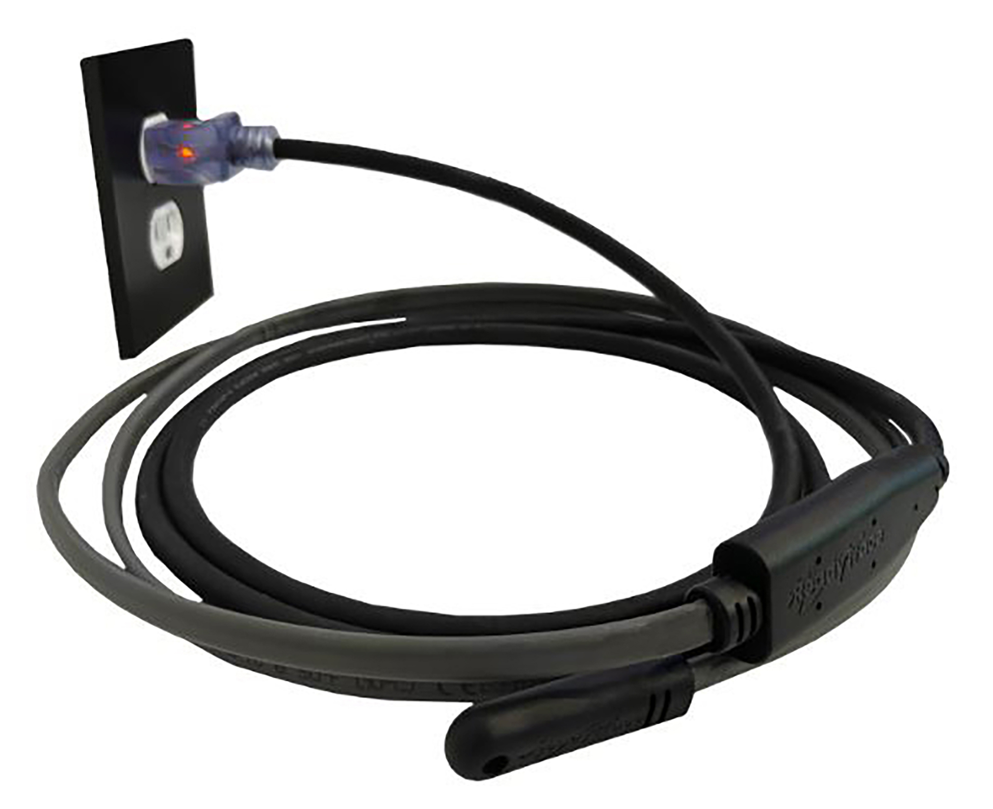
Powertrace by Powerblanket offers self-regulating trace heat systems that feature a temperature-dependent resistive element housed between two parallel conductors that automatically limit the output according to the surface to which it’s attached. When the surface temperature increases, the power output of the heat trace decreases, and vice versa. This technology prevents overheating and damage to the protected processes.
Primary applications of heat trace are freeze protection and temperature maintenance. Expansion or freezing of water and other liquids poses a safety concern and can also be damaging to equipment and workers. Proper heating of liquids at a specific temperature range allows you to cost-effectively transport liquids, maximizing efficiency and simplifying your processes.
Keep your pipes from freezing and maintain ideal temperatures for peak efficiency. Our made-to-order heat trace solutions are completely customizable to your specific application.
If you're seeking a commercial, self-regulating option, shield your critical systems from freezing with intelligent self-regulating heat trace that adapts to temperature changes and protects your assets.
Shop Our Ready-To-Ship Heat TraceWhat does a completed heat trace system look like?
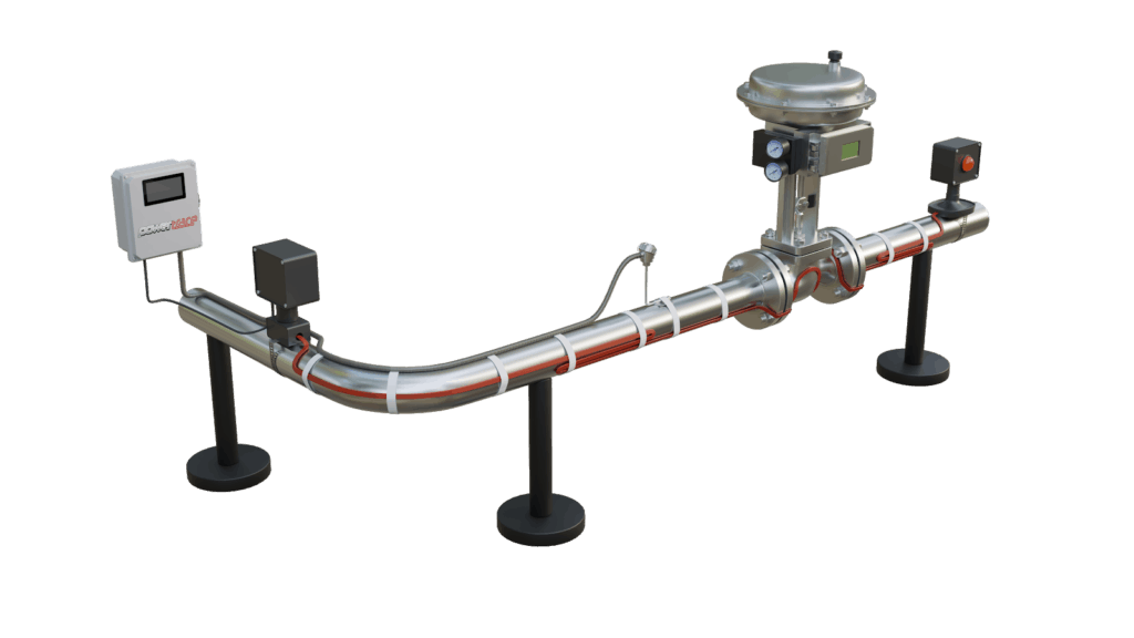
Check out the diagram below to see what a completed heat trace system entails. A heat trace system includes:
- Heat tracing cables (self-regulating heating cables, constant watt cables, or power limiting cables) applied to piping and tanks, often secured with fiberglass or aluminum
- A control panel or thermostat
- A power connection box to connect power from the breaker
- Ambient temperature sensor
- Insulation jacket
- Light indicators to monitor output
- Cable termination box
How do you install heat trace?
While these tips and instructions apply to typical heat trace system installation, refer to manufacturer instructions for product-specific installation instructions.
Pre-Installation
Before installing any electric heat trace, it is essential that the user verifies the following: first, be sure that you’ve selected the correct heat trace and accessories in regard to the calculation of heat losses, maximum permissible operating and ambient temperatures, class, and length. Next, ensure that all piping is installed correctly, is in proper working order, and has been pressure tested.
Walk the length of the piping system to determine the route of the heating cables. The surfaces in which the heat trace will be attached should be free from dirt, rust, and any sharp edges or objects. Remove old heat tape and any other combustible materials.
You’ll need a pair of wire cutters and an insulation resistance meter with a minimum testing voltage of 500 Vdc and a maximum testing voltage of 2500 Vdc.
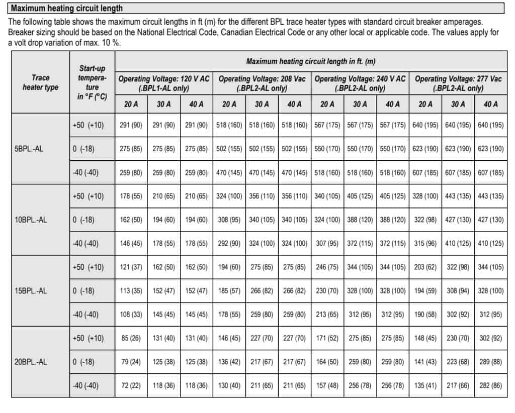
Take care to determine the maximum cable circuit length allowed for your specific system. We’d love to help you with this, so give us a call or check out one of these charts to calculate the total cable heating length.
Once you’ve confirmed that heat trace cable is the proper type and output, check for any damage to the cable and test electrical integrity using a megger (see specific included instructions for more details).
Heating cable can be cut to the user’s desired length. Heat trace cable is then combined with termination and splice kits, tee kits, end seals, and other accessories to complete the system.
Installation
Next, pay for the cable along the pipe to be traced. Roll the cable out loosely while keeping it near to the piping. Doing this will ensure you have the appropriate amount of cable and account for all components, elbows, loops, and fixtures. Allow excess cable (12-18” per termination is recommended) for splicing, power connections, or any future servicing. Any adjustments in circuit length will require reconfirmation due to the change in power output, so be sure to cut to the exact desired length. For better heat distribution of heat trace on plastic pipes, first apply aluminum tape to where the trace cables will be applied.
Begin attaching the heat tracing cable to the pipe on the lower half of the pipe at a 45° angle (looking at the pipe straight on, attach a single cable at 4 o’clock and if using an additional cable, at 8 o’clock). Attach the cable using heat or fiberglass tape every 6” to 1’ back toward the power source.
An extra heating cable is required for any flanges, valves, etc. For installation suggestions for placing cable around flanges, valves, or supports, refer to heat tracing cable installation instructions and project designs for the most accurate and task-specific details and information.
Heat trace systems can be controlled with a simple thermostat or with a temperature sensor like an Rtd that provides feedback to a more common PID or PLC-style controller. These systems will control and adjust the temperature of the heat trace. Additionally, most are equipped with varying types of monitors to assist the user in observing power output.
Before cutting the heat tracing cable, ensure that it is fully attached and that appropriate allowances, generally 1’ minimum, have been given for connections and terminations. Once the heat trace has been cut and installed on the pipe or tank, carefully follow manufacturer instructions for termination. Confirm that the tinned copper overbraid is separated from the two busbars and that those busbars are firmly secured into their proper termination points.
Proper insulation covering the heat trace cables and thermostat is an important feature that cannot be forgotten. Additionally, maintaining the integrity and overall well-being of an insulated system is critical. Check out this article that mentions the dangers of compromised insulation. Prior to installing insulation, visually check that all cables, splices, and power connections are in working order and free from mechanical damage.
How do you connect heat trace cables?
Before beginning the connection, test the heat trace cable to ensure integrity with a megger of at least 500 Vdc. To do so, connect the positive lead of the megger to the cable’s bus wires and the negative lead of the megger to the cable’s braid. Again, refer to specific system requirements. Before making any power connections, first make end and splice connections.
Heat trace can be connected to 120V, 208V, 240V, or 277Vac, and to any size breaker.
Still have questions?
Heat tracing systems are an effective solution to freeze protection and temperature control. If you still have questions concerning your new heat tracing system or would like more in-depth instruction, reach out to us at (844) 260 8891 or [email protected]. Our custom design team will walk you through our made-to-order heating solutions that will optimize your product performance and put your worries to rest.
Frequently Asked Questions
What is the NEC code for heat trace cable?
The NEC code for heat trace cable, specifically NEC 427.22, requires that heat trace tape be equipped with a ground fault equipment protection (GFEP) circuit breaker to ensure safety.
How do you secure a heat trace cable?
To secure a heat trace cable, use fiberglass tape to attach it to the surface being heated, and consider using aluminum tape on PVC pipes to enhance heat distribution.
What should be done with a trace heater before it is installed?
Before installing a trace heater, ensure the piping system is checked, determine the length of the pipe to be heated, select the appropriate heat tracing cable, verify the power supply, gather necessary tools, clean the surface, and then mount the heat tracing cable.
Don't let the cold weather stop your business. Powertrace heat trace cable will keep you running smoothly no matter how low the temperatures.
