
Electric heat trace installations happen in your facility all of the time. How do you know that your installation is a good or bad one? As winter looms near on all of our calendars, how can you know that the system that you have installed should work the way it’s supposed to?
Before we get started, let’s discuss what failure means with regard to heat trace. In no uncertain terms, failure of a heat trace system means that the system as installed does not protect your facility from freeze ups or does not maintain the proper temperature. These failures are expensive in the form of lost product, increased maintenance cost as well as possible safety issues.
Some of the most common reasons for heat trace failure is:
- Poorly installed insulation
- Bad installation maintained (or lack of maintenance)
- Improperly sized heating system
- Poorly executed project with unqualified system installation
- Inadequate Control system
- See more reasons for failure here: biggest fails in heat trace
Many heat trace failures can be prevented by performing an audit of your system on a regular basis. Understanding how to conduct a proper, comprehensive audit will ensure your system is providing reliable heat output for years to come.
If you're seeking a commercial, self-regulating option, shield your critical systems from freezing with intelligent self-regulating heat trace that adapts to temperature changes and protects your assets.
Shop Our Ready-To-Ship Heat TraceHow to audit heat trace systems
Every heat trace audit mainly consists of walking along your heat trace system. During the auditing process, you’ll want to keep an eye out for situations that either are already compromising your system’s temperature maintenance plan, or have the potential to do so. This process can be summarized into four steps: installation, insulation, power and electronics, and minor troubleshooting.
Installation
Auditing your heat trace system starts with knowing how to install heat trace. A properly installed heat trace system consists of a controller, temperature sensors, heat trace cable and related accessories, and the insulation layer that covers all of the above. When performing your site walk audit, confirm that each step of the installation process was performed correctly.
Installation errors
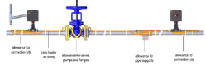
Too often, heat trace systems are installed incorrectly or, resulting in temperature-sensitive parts failing and materials becoming unusable. Common installation errors include not allowing extra heat trace for flange pairs, valves, pumps and incorrect cable orientation on the pipe. Failure from incorrect cable orients happens based on the false idea that heating cable needs to be wrapped or spiraled around the pipe. It used to be done that way, and in some rare cases a spiral wrap is still used, but for most industrial applications a straight run is all that is needed.
The right place for heat trace
However, where that run is installed is critical. If there are two places that you do not want to install heat trace on a horizontal run of pipe, it’s at the very top (12 o’clock) or the very bottom (6 o’clock). But why is that?
- 12 o’clock wastes heat. As heat rises, any heat generated while the heat trace is at the 12 o’clock position is wasted away.
- 6 o’clock seems great, but in some cases and with leaky insulation, you don’t want that heating cable in water or liquid. . Heat trace that is installed in the 6 o’clock position is almost guaranteed to get wet and eventually fail.

The optimal place to run a single cable is at 5 o’clock or 7 o’clock. Some applications required double runs, which in those cases you would use both.
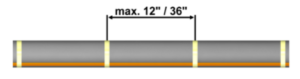
Be sure to notice if the heating cable is properly installed along the length of the pipe as well. Be sure that it is taped in intervals of about 12”, and that the cable is tight up against the pipe.
High-temperature glass cloth tape normally comes in two ratings, and those are designed to cover both very low and very high temperatures. If your piping system is in an environment that will have either of these extremes, you want to make sure that you use one of the two listed types of glass cloth high-temperature tape.
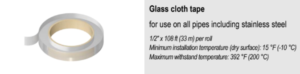
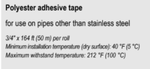
Using this tape will ensure that the adhesive will be able to endure these temperature extremes. Common substitutions include electrical tape, fiberglass reinforced packing tape and even zip ties. Be sure the right tape is used so it won’t easily melt under direct heat.
Finally, the tape should be installed by wrapping one complete wrap around the heating cable, and then 1 ½ wraps around the pipe.
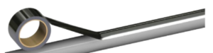
If your pipe or surface is plastic or PVC, be sure a run of high temp aluminum is installed beneath the heat trace. This is critical for a couple of reasons:
- The Aluminum tape (high temp rated) will distribute the heat more evenly across the plastic pipe, allowing for the heat to be spread out.
- PVC Pipe no matter the schedule is rated for a given temperature at a given pressure. If your heating cable exceeds that temperature, the piping pressure is derated.
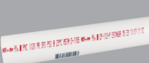
PowerTrace PTAT80-164 High Temp Aluminum tape being applied to PVC:
Pressure rating is a “burst” pressure, and it is rated at a specific temperature. Above you can see 370 PSI @ 23C (73.4F). Heat trace on the coldest day of the year to keep the contents of your PVC pipe from freezing will be putting out much more than 73.4F. Once you go over that temperature, your PSI rating decreases. How low can you go?
Service Loops: all of that extra cable!
Each power connection and end seal kit will take 1 to 2 feet of extra heat trace. This is needed both to strip the cable for termination as well as leaving a little slack in the cable so that if you ever need to replace either type of kit, it will be easy to do.
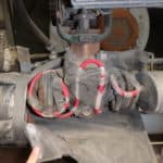
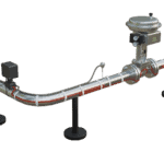
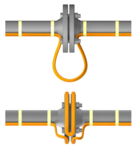
Each valve, flange pair, pump and pipe support should also have a service loop. Service loops not only make it easier to repair or replace the part the heat trace is wrapped around, it also puts more heat on those items because they have more mass and will affect the thermal integrity of the system. Actual specific calculations for each of these items can be provided by way of an IEEE Certified Heat Trace calculation system offered by every single viable heat trace manufacturer. See the examples below:
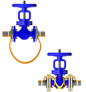
Valve Sample

Pipe Supports
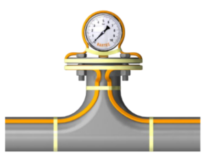
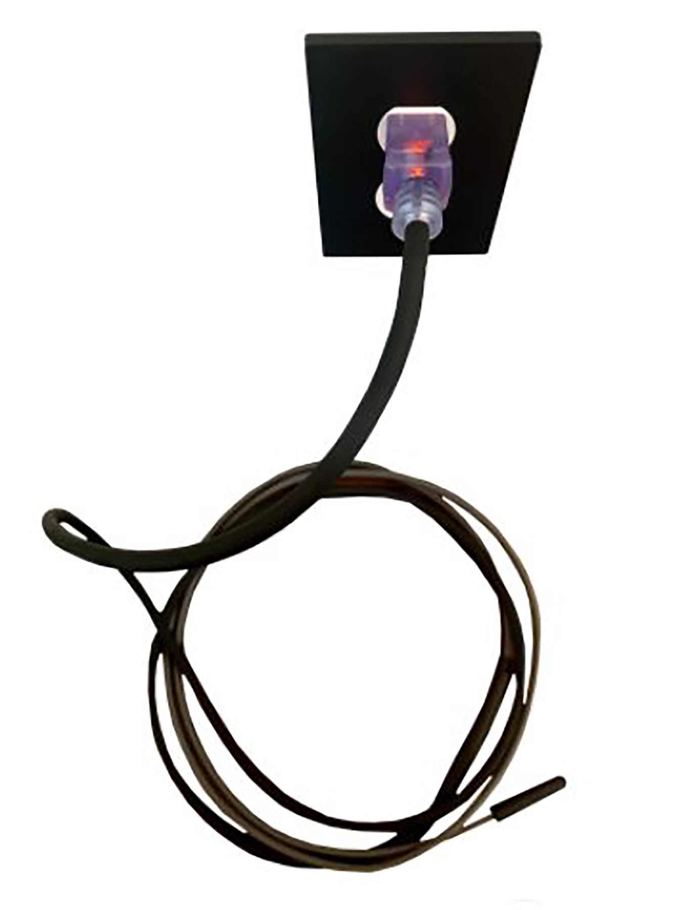
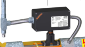
Liquid Filled Pressure Gauge
Did you find any problems?
Ideally, your heat trace system will look exactly the same during your audit as it did when it was first installed. If anything appears to have been altered or damaged, give particular attention to these areas as they are most likely to impact your system’s temperature maintenance. We’ll revisit issues you might have discovered in the fourth part of the audit, “Minor Troubleshooting.” For now, let’s move on to the next audit topic, “Insulation.”
Insulation
The most common failure for heat trace as a system is poor or compromised thermal insulation. Heat trace manufacturers will focus on the heat trace and when the heat cable itself actually fails- not the whole system and when the system fails. You can have perfectly healthy heat trace installation but bad insulation, which will result in your equipment freezing up as hard as rock.
Inspecting thermal insulation
Inspecting insulation is easy. This can be done by performing a few key steps:
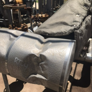
- Visually examine the outer jacket of the insulation. Search for signs of visible wear and tear. See if there is any potential damage that would cause water to be able to get into the insulation just below the outer jacket. Are there dents, gaps, any holes at all?
- Where possible, inspect the insulation just below the outer jacket. Are there any signs of water? If there are drains installed in the outer jacket, open them up and see if any water has collected. Here are a two examples of how water might work its way into the insulation:
- Is the seam of the outer jacket on the top of the pipe? Often, that’s the most convenient way for the installer to put it on, but water can get in and kill your insulation.
- Are there dents or damage that have made holes or pathways in your outer jacket? Water can seep through these openings and ruin internal layers of insulation, costing you time and money to replace it.
- Finally, check along the length of the installation. Are there any missing gaps of insulation? It is very common to see removable insulation jackets that have been removed and not reinstalled.
Pay attention to the insulation as you check to see if it’s covering the heat trace cable properly. If the insulation has been applied correctly, you will only see the power connection kits, possibly the end seals, and (of course) the outside of the insulation.
Example of thermal insulation left off of the pipe/valve system:
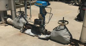
What’s the point of having insulation on the valves but not the equipment in between them? Every part of your system that utilizes heat trace requires insulation.
Example of damaged insulation that is compromised and possibly has let water into the insulation:
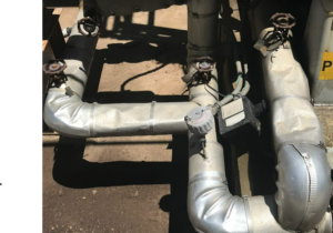
Notice also the removable insulation jacket on the top right of the right image, as it is incorrectly oriented. Water will get in there.
Example of thermal insulation left off of a pipe, exposing the heat trace cable:
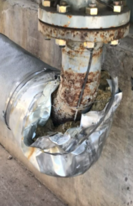
Damaged insulation
Damaged insulation that allows a tracer (steam trace, electric trace) be exposed to the ambient environment. It does not make any difference at all how much wattage or BTU is being applied. The heat trace cable is not effective without insulation. If there is any insulation damaged, missing, or if it’s improperly attached to the heat trace, make a note of it so it can be taken care of in the troubleshooting step of the audit.
Inadequate or improperly installed control Systems
Controllers and sensors make up key parts of your heat trace system. Without them, you wouldn’t be able to regulate temperatures along your heat trace cable or see what the current temperature is where the heat trace cable makes contact with your equipment. Additionally, you need to be sure your heat trace cable can carry the needed amount of power down the line through the end of your heat system. You can check that by doing the following:
Make sure that proper voltage is being applied. The best way to do this is to first test at the breaker. Check the integrity of both the power coming to the breaker at the breaker panel, as sometimes power to the facility is not what you thought it was. This reduction or over supply of voltage can cause problems with heat trace heat output. Following this step, energize the circuit and check the voltage at the end of the heat trace run. This is done at the end seal, or end of the heat trace run. Confirming that voltage is acceptable at the end of the run from the supply is key in ensuring that the system has the needed voltage to perform. Voltage checks at the breaker are a primary checkpoint in any troubleshooting plan.
Ensure that properly rated breakers are installed and in working order. Each heat trace circuit run should have documentation showing required voltage and current or amperage being pulled for each circuit. Breakers should be properly rated for the load per NEC and Local code. Keep two things in mind with regard to breakers:
- Self Regulating Heat Trace has an inrush effect. It will pull 2-3X amperage on start up. If you had a 20 amp run of self regulating heat trace on one circuit, it would blow the breaker. Maximum allowance for most 30 amp heat trace circuits is in the 10-12 amp range.
- GFEP 30mA Breakers must be used on Industrial Heat trace circuits. Not 5mA GFI breakers. A Square D QDB breaker is a good example of a correct breaker.
Knowing the amperage of each of your heat trace circuits and how to properly size breakers is key in a good troubleshooting plan for heat trace.
Check the resistance and wiring of the circuit from the load side of the breaker. Knowing each circuit’s required resistance is essential. From the breaker, check all of the wires, terminations and heat trace. All of these components are required and critical in running a heat trace circuit. Not checking them all as a system would be a mistake in your troubleshooting efforts. Using a multimeter, check to see that the resistance is equal to the originally installed number. Heat trace can look just fine, but lose it’s ability to create heat.
Meggering your entire system is one of the best ways to troubleshoot heat problems. Start by meggering each circuit from the load side of the breaker. Following megger instructions, proper evaluation using a megger from the control panel is critical. You will be checking the wire, all terminations and the heat trace from the load side of the breaker. This allows you to test not only the resistance to ground of the heat trace, but also the resistance to ground of the wire going to the heat trace. Wire and termination in junction boxes can have potential leakage to ground. This can cause your breaker to trip and shut the system down.
Megger the heat trace at the power connection, and be sure to follow megger and heat trace manufacturer instructions. Isolating the individual heat trace circuit will allow you to make sure that the individual heat trace circuit actually is not close to a short to ground, or has resistance to ground. The ideal megger reading is 2000 megohms on a 1000 Vdc. setting. Manufacturers will tell you that anything over 20 megohms is acceptable, but keep in mind, 20 megohms is not perfect resistance to ground. Consider replacing that run of heat trace if anything between 20 and “infinite” are seen.
Using Control in the first place
There is a common misconception within the world of industrial heat trace, and that is that self regulating heat trace does not need control. This could not be further from the truth. The truth is that self regulating heat trace can regulate it’s output as temperature rises and falls, but it cannot turn itself on and off. Some form of controller really should be used on a given run of heat trace. Thermostats, RTD or Thermocouple going back to a controller, or a run from a breaker (GFEP Rated with a 30mA trip) that is controlled by some sort of temperature regulating control will do the trick. If you don’t do this, your heat trace will pull amperage all year round. This is both a waste of electric power as well as wear and tear on the cable itself.
Sensor placement is critical in the proper running of your system. If you have chosen to use some form of temperature control for your system, is the sensor that provides the feedback in the “right” place? Make sure that it is in a location where it can read the temperature as it goes into your process, or where the pipe will be the coldest (Up in the air vs down on the ground for example). Sensors are often places where it is most convenient to the installing contractor, not where it makes physical/thermal sense.
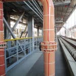
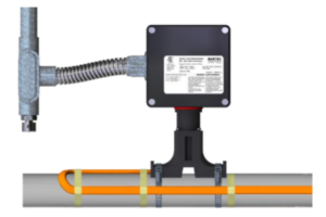
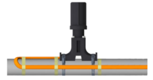
Check Power Boxes and End Seals
A great maintenance practice is to simply open your power and ens seal kits. Is there water in them? Bird nests? Also check to see that a “Drip Loop” is used for the conduit coming into the box. Moisture can accumulate in the conduit along its length. If the Power Kit is the lowest point along the conduit system, it will fill up with water. Note in the image below how the conduit slopes down and away from the selected power kit:

Minor Troubleshooting
As you’ve conducted your audit, you might have noticed situations in places across your heat trace system that needed repair. Troubleshooting heat trace isn’t a difficult task once you’ve completed the former steps of the audit because at this point you know exactly what’s wrong and how to fix it. Whether it’s a tear in the insulation, an improperly installed controller, or a malfunctioning sensor, this final phase of the audit is the right time to address these issues.
You know your heat trace system is in good shape when the following criteria are met:
- dry effective insulation
- a reliable power source
- the ability to create heat or have resistance
- resistance to a ground or not have potential to short out
- power and end seal kits installed properly and water tight
- Proper control and sensing
Without any of these features, electric heat tracing will be less effective and become damaged over time. Don’t let your freeze protection plan become compromised due to inoperable heating cable.
We Know Electrical heat Trace
Call Powerblanket today for help in troubleshooting your heat trace system or replacement of non-working cable with PowerTrace. Our technical expertise and relationships with electrical and insulation installers across North America can help answer any questions you have about your insulation system.
Frequently Asked Questions
Does heat trace need to be on GFCI?
Yes, the National Electrical Code (NEC) requires heat tracing systems to be protected against ground faults using Ground Fault Equipment Protection (GFEP) circuit breakers, which are different from standard GFCIs used for personnel protection.
What is the NEC code for heat trace?
The NEC code for heat trace, specifically NEC 427.22, mandates that heat trace systems must be equipped with a ground fault equipment protection (GFEP) circuit breaker to ensure safety and prevent electrical faults.
What is the life expectancy of a heat trace cable?
The life expectancy of heat trace cables typically ranges from 3 to 5 years, depending on usage and environmental conditions.
What is the problem with heat trace?
A common problem with heat trace systems is circuit breaker tripping, which can occur either immediately upon power-up or after a few seconds of operation, often due to issues like improper installation or insulation failures.
Don't let the cold weather stop your business. Powertrace heat trace cable will keep you running smoothly no matter how low the temperatures.